How to Read this Blog

When I started this blog, I could not figure out, within the given parameters, how to get it to read logically. So it ended up with the freshest post on the top of the page with the top of the post being the beginning of the post. When you get to the end of the post, you will find the beginning of the previous post. A bit awkward, but ...it is what it is. (right David?)

Also, feel free to leave comments. I engaged the annoying "real person verification thingy" because some dork put an add to his product on my blog and disguised it as a comment. He probably works on wall street.

Sunday, April 26, 2009

Here is the new release bearing clipped into the release fork. The fork can actually be installed backwards, so care must be taken to get it right. The stamped part number, near the tape part number on the fork, needs to be down. It goes on the picot side, not the slave cylinder side. On mine, this actually put the number upside down.
Hanging from the engine hoist, ready to go in.
Splines engaged, searching for the pilot bearing.
She's home. Chain is slack.
The block is bolted to the cross-member. The transfer case is mounted-up. The taped-up u-joint is on the 1977 short drive shaft with the carrier bearing. You can see that it is the wrong u-joint. Something to deal with another day. That short shaft will most likely be a custom length anyway. I will need to fing a replacement yoke when I get it modified.
Another angle.
And...the other side.
Not sure what to do next. I need to strip the new cab of the flooring and dash and take whatever is remaining off the firewall. I also need to deal with some rust issues on the core support and modify it to accept the ctd radiator and the second generation Dodge Cummins intercooler. I am still hoping to get my 1975 grill over the intercooler, but I won't know about that for a while yet.

New Southbend Clutch

OOOOH! Lookie what Uncle UPS brought.
This clutch is rated to 400 HP an something like 700 ft/lbs of torque.
It took about ten minutes to get the packing off the flywheel. The flywheel comes with I nice pilot bearing already installed.
I do not know if it was an oversight, but this kit did not come with a pilot tool. Luckily I had borrowed one from M&H Machine.
I got all 60# of the flywheel bolted up and torqued down with locktite. You can also see the started is now in place.
Here the pressure plate os torqued dwon. I took a few minutes to level out the spring fingers where they meet the throwout bearing.
Its starting to look like a nice little package.

Thursday, April 23, 2009

Cross-member and tranny-mount

Here is the donor tranny cross member in its new location, one hole toward the stern from the old member.
This is a shot of the new tranny-mount rubber bushings with part numbers.
Crappy shot of the new mount location. the square tube on top of the bracket is at least three times thicker than the cracked one I took off. It is also longer, so the holes are not as close to the edges.


Tranny Mock-up to Configure Cross-member and Mount.

I started by attaching the adaptor plate to the back of the block.
One of these holes on the left side of the adaptor plate is for the barring tool that is used for holding or rotating the engine. I do not know what the other is for. I will need to find or make covers.
This hole on the left is for the starter.
Now the bell housing. This is just a mock-up. there is no flywheel or clutch under there. You can also see the stock cross-member, minus the mount, for the 440/727 combo.
Swinging in the NV4500 (not yet gussied-up for the dance.).
With the tranny bolted up, I clamped the diesel member in next to the original for the crewcab. They are exactly the same depth, but the dirty one is much beefier. I like beef.
Some quick measuring told me that I will be able to use the rear two of the three holes in the frame and will only need to drill one set of holes to relocate the cross-member. I will also get rid of this twinky piece of square tube. It is stress-cracked almost the whole length on both the top and bottom. It is close to two pieces.

The best news of the day

Ever since I bought the donor with the NV4500 transmission, I have been unsure as to whether the truck was originally a Getrag 5-speed or an A518 automatic. Since it did not have the heat exchanger on the side of the block ot a throttle positioning sensor on the injection pump, I hoped it was an original 5-speed. I knew the current 5-speed was a replacement because it was not a Getrag. My doubt came because the three screw/bolts on the AFC that hold the cover on and also hold the TPS bracket on auto trucks were missing. The reason I was concerned is that the transfer-case input shafts on the auto trucks were significantly smaller and weaker than those for the stick trucks. The automatic equipt trucks have a 23 spline input to the t-case, the 5-speeds came with the beefier 29 spline input.
While I was waiting for my clutch to come from Uncle UPS, I figured I would sepparate the tranny/t-case so I could mock up the tranny placement and figure out what kind of cross member issues I will have.
Gloryosky Batman! I count 29 splines. Thats money I don't need to spend. Both the input on the t-case and output on the tranny have the same 29 spline count!


New Rear Main Seal

Now that the 1200# monster is off the engine stand I can get to the rear main seal. Once again, I will appologize for the poor quality of my pics. If you want to sponsor this site, send me a decent camera. Kidding, of course.
The way to do this, without removing the rear housing and damaging the oil pan gasket, is to drill two 1/8th inch holes i80* from each other in the seal. Be careful not to score the crank or the aluminum housing with the bit. Just centerpunch and drill.
Then I used my slide hammer. You can also drive in a couple of sheet metal screws and pry it out with screw drivers or wiggle it out with vise grips.
Working from side to side and using gentle taps with the slide, I eased it out evenly.
Out.
After getting it free, I cleaned the surface on the crank and on the housing with brake cleaner on a rag threaded over a screwdriver. The wear on the crank from the old seal was not that bad. I planned to drive the new seal in a little deeper than the old one so the seal lips would ride on new material.
The new seal comes with this stepped pilot tool to ease the sealing lips over the end of the crank without folding them over causing the new seal to fail. The seal is installed dry.
Ince the seal is started on the end of the crank, the plastic tool can be removed and this tin tool can be used to drive the seal in straight. I drove it in until the tin tool was flush with the end of the crank and it put it right where I wanted it.
The finished product.


Time to place the engine.

Thar she blows, hangin' by a chain again.
Next to take off the hanger from the monster engine stand.

Slips in right like it was intended to be there. No modification to the cross member or motor mounts.

Saturday, March 28, 2009

Please forgive me.

If you go back to the original post on this blog, you will see the truck with the Super Bee decal and stripe. When I originally built this truck with the 440, I tried to stick with a 1969 Super Bee theme. The color was a correct Mopar color for the Coronet Super Bee. The gas caps were from the muscle car era. And the stripe is the classic Super Bee touch. At that time, I painted the Dodge v-8 blue 440 to a nice Hemi orange. For over a decade, we have simply called this truck the "Super Bee." So holding to the tradition, I nixed the Dodge Cummins Black and the Cummins correct baby poop tan colors and went with the Hemi orange.
Her is the engin with frash paint. I ran out of orange before I got to the oil pan.
I love the way the contrasting colors make the orange pop. I went with black on the oil pan. The chances of having this engine leak proof are slim so I thought black would be fine for the pan.
Right side.
Right again.
Top.
Yep.


More engine teardown.

Cleaning-up the engine and getting ready for paint, I wanted to remove as much as possible that was easy. I like the way an engine looks when the base (block) is freshly painted and the accessories stand in contrast to the base color.

To get to the top inside nut on the power steering pump, I had to modify a 15 mm wrench. Luckily, in my toolbox I was able to find a cheap loner wrench. A few seconds with the torch, and I was able to get right back to work. (unfortunately, I left the acetelene bottle on and now it is empty. Doh!)
My custom wrench.
In taking the fan off, I did a little experiment to see how thick my skin is. Poor little guy.

Dowel pin tab.

I ground this tab out of a large washer.

After using a sharp chisel ti open up the space between the bolt and the pin, I inserted the tab. Then I removed, cleaned, and retorqued the timing case to block bolts using locktite.

Friday, March 20, 2009

Timing cover removal.

Today I finally got back into the shop for an hour. I had been laid up with the flu for a few days, but now I have a week off. Other than a trip to Seattle, dropping a few trees, helping my son with his science project, and nursing my back, I have nothing to else to do.

I started by removing the dampner. The unmistakable smell of locktite, not to mention the hernia in my gut, tells me these bolts were put in to stay. (note to self: Get the four dampner bolts off the head and into a labeled bag, Dummy.)
Having removed a cummins timing cover before, I knew there were different length bolts holding it on. Some go through the cover and case and into the block (long). Others just hold the cover to the case (short).

To avoid confussion upon reassembly, I made a map of the cover. At the bottom I traced each size bolt and labeled the long bolts "1" and the short "2." I also indicated any "special" doodads different bolts, such as on extended "1" and one extended "2" that hold the factory tach pick-up.
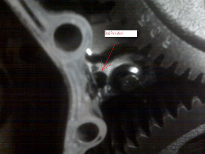
The first thing I checked upon removing the timing cover was the infamous killer-dowel-pin (KDP). This dowel is used by the factory to aid assenbly. Other than that its only purpose is to, perhaps, strengthen the block to case attachment. The dowel pin won its name, Killer, and its infamy from its habit of backing out of its home and taking a ride through the timing gears. Personally, I make a habit of "killing" the KDP anytime I have the timing case open or if I even have easy access, such as if the rediator is out. The KDP can be killed by either peening the aluminum case around the dowel pin hole with a punch or by fabbing a tab to cover the hole. The tab can be held in place by the case attachment bolt immediately to the right of the pin.
I am getting tired of my crappy camera, but I don't dare take the wife's camera out into the grease. Anyway, this is my before image. I was hoping you would be able to see that the end of the pin was on the same plane as the shoulder of the neighboring case bolt.
After tapping on the pin with a punch, it went in about 3/16 of an inch. It is generally assumed that the dowel pin is bottomed out upon assembly. I do not know if this is the case, but if it is, mine was on its way out. Not knowing how many miles were on this engine, I have no way of knowing how much time before...Boom. My guess issomewhere around a million more miles. If its only gone 3/16 inch in most likely 2-300,000 miles, it was not in a hurry.
Another note: The last pin I killed, on my ramcharger project, some of the case bolts were loose. I mean, not even finger tight. One of these coming out will do as much damage as the dowel pin. It is also standard procedure to clean the bolts and holes and retorque them with locktite. The crank needs to be rotated to expose hidden bolts behind gears.
I an not sure but it looks like the outer lip on the cover seal was wearing too close to the end of the crank. It was clearly leaking. When I replace the seal, I will set it a little deeper in the cover.
A point of curriousity: When rotated, the timing mark "0" on the lower gear will line up with the "E" mark on the upper gear. I will head over to http://www.dieseltruckresource.com/dev/forumdisplay.php?f=93 to see if this is staight up or if it is a tooth off as I expect.
EDIT: my research shows that I am timed correctly.
A pic of the gears waiting for me to get back at it.